
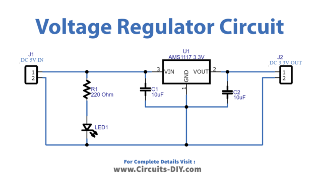
Voltage Regulator Circuit Circuit Diagram A voltage regulator can take those 9V as input and create a nice and stable 5V output that you can use to power your device. Or if you need different voltage levels for a circuit you're building. Let's say you have a circuit with a microcontroller that needs 5V and a motor that needs 12V.

A linear regulator operates by using a voltage-controlled current source to force a fixed voltage to appear at the regulator output terminal (see Figure 1). The control circuitry must monitor (sense) the output voltage, and adjust the current source (as required by the load) to hold the output voltage at the desired value. The
Voltage Regulator Tutorial Circuit Diagram
The purpose of a voltage regulator is to provide a constant output voltage regardless of the load resistance. In other words, an ideal regulator would produce a voltage that is (for example) exactly 3.3 V when connected to a 100 kΩ load and exactly 3.3 V when connected to a 5 Ω load.

Next up in our voltage regulator tutorial, we need to talk about some additional caveats of using voltage regulators that you should be aware of. If you do the math on a 5 volt circuit drawing 500 milliamps (or .5 amps) with a 12 volt input voltage, that turns out to be 3.5 watts of heat generated (or wasted). If you're looking for lower

How to Make Voltage Regulator Circuits Circuit Diagram
These circuit projects using discrete parts can be in the form of of permanently fixed or constant voltage, or stabilized adjustable output voltage. What is a Voltage Regulator The main function of a DC voltage regulator circuit is to generate a voltage and current that is fixed and constant at a certain specified levels.
