Sensor Gyroscope Circuit Diagram The MPU-6050 IMU (Inertial Measurement Unit) is a 3-axis accelerometer and 3-axis gyroscope sensor. The accelerometer measures the gravitational acceleration, and the gyroscope measures the rotational velocity. Additionally, this module also measures temperature. This sensor is ideal for determining the orientation of a moving object.

Gyroscopes and accelerometers can stabilize objects, while magnetometers can make digital compasses. GPS sensors can track an object's location, and ultrasonic and IR sensors can detect objects for landing and obstacle avoidance systems. Explore the tutorials below to learn how to use these powerful sensors! Senor is ready to read the values and to get the reading we create sensor event sensors_event_t a, g, temp; and store reading in them using mpu.getEvent(&a, &g, &temp). start printing stored values using a.acceleration.x/y/z for acceleration , g.gyro.x/y/z for gyroscope and temp.temperature respectively.
Motion and Position Sensors Circuit Diagram
Gyroscope sensors are essential components in modern technology, known for their ability to measure and maintain orientation. Found in devices ranging from smartphones to aerospace systems, these sensors allow precise motion detection and stabilization. They are particularly useful in applications where tracking orientation, rotation, or

Using the ESP32 & BMI160 Accelerometer and Gyroscope Module, we can develop a C++ Code to read the Acceleration values. We have converted the raw readings into acceleration using the mathematical equations. The following code initializes the BMI160 sensor using I2C communication. It sets the accelerometer to normal mode.

6050 Accelerometer and Gyroscope Tutorial For Begineers Circuit Diagram
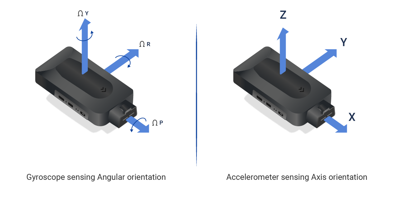
3-Axis Gyroscope. MPU6050 has a 3-axis gyroscope that uses Micro Electro Mechanical System technology to measure rotational velocity. The gyroscope consists of a tiny mass that moves back and forth in response to rotational motion. As the mass moves, it causes a change in capacitance, which is detected by the MEMS sensors.
Motion tracking sensors are used in applications like robotics, gesture recognition, vehicle stabilization, position control in drones/quadcopters, pointing devices, game controllers, and fitness tracking devices. One of the popular motion tracking sensors is MPU6050. It is a six-axis MEMS motion tracking sensor that includes a MEMS accelerometer and a MEMS gyroscope. The sensor also has…